|
|
Post by grossmsj on Jan 20, 2022 19:20:36 GMT -5
I just started using my 4-th axis rotary kit today. After some initial failures, I came to understand the XY origin should be set to the midpoint of the piece, rather than relative to the headstock. I'm not crazy about defining the origin this way, as it seems like you have to go through this process for every piece.
I'll probably use the 4-th axis rotary kit a lot. I'd like to put the headstock in place and just leave it there. Then, I'd like to define an origin that is a small, fixed distance from the edge of the chuck. This way, the origin is constant for every piece I put on there regardless of length. There might be a good reason Axiom chose to do it the way they have, but it's not obvious to me.
So, two questions:
1) Is there a way to define the origin as fixed and workpiece independant?
2) Am I missing the advantage of defining the origin based on workpiece dimensions?
|
|
|
|
Post by joeblow on Jan 21, 2022 5:22:52 GMT -5
Hi Grossmsj. There sure is a way to do this and it is very useful. I have an AR6Pro with the B18 HHC and can set 9 different work state coordinates, origins, by pressing Menu + (1-9) on the keypad. If you have this controller you will see a number (1-9) at the beginning of X, Y, and Z that shows what coordinate state you are in. For example...after homing, your machine will display "1" in front of each axis. This is work coordinate state #1 and you can set your origin in this state and never change it again if you choose. Let's say the next job you want to run is a non-rotary job. Press menu+2 and you will now see a (2) displayed in front of each axis on your controller. You are now in work coordinate state #2 and can set your origin and proceed with the non-rotary job. Need to go back to the rotary for further work or another job, press menu + 1 and you will be right back to the origin you set for the rotary.
I use work coordinate state #1 for my rotary and have also set work coordinate state #2 with the exact same origin as #1 just in case I slip up and accidently change the origin in work state #1. This way I can go to work coordinate state #2 and recover my rotary origin. This has saved me quite a few times. I also placed the headstock with chuck just a tad outside the machine limits. This way you will not accidently run your bit into the chuck. Been there done that. With longer pieces you can simply slide the tailstock back and utilize the same origin you set in whichever work coordinate state you choose to utilize for rotary. Just remember to set your origin in the software you are using to the same location as the origin you set on the machine.
As far as question #2....nope, don't see any advantage to setting origin in the middle of the workpiece on the rotary. Perhaps someone else does and can explain the benefits of this.
|
|
|
|
Post by grossmsj on Jan 21, 2022 13:41:56 GMT -5
Thank you joeblow, this is really helpful. I appreciate the detailed answer, especially when it comes to the Rich controller. It is a bit obtuse at this point. It looks like we have the same machine setup, which is fortunate for me as I expect you may hear from me again.
My first attempt with a fixed origin gave me the 'softlimits' error. I understand this error is a bit of a rite of passage for newbies. So I reverted to mid point and got a cut, but only through 90 degrees of rotation. Some Googling led me to change the RT Type parameter to normal and I got the expected full rotary cut. But I'll go back and try the origin setup again. Add my name to the list of users that wish Axiom put a bit more detail and accuracy into getting started.
It occured to me putting the chuck 'off limits' could turn the softlimits check to my advantage. That's a good idea too. Wonder how many bits I'll break in the coming year... :>)
Thanks again,
Scott
|
|
|
|
Post by aluomala on Jan 21, 2022 18:19:02 GMT -5
To piggyback on Joeblow's advice (using work coordinate states), what I have done is set my x0y0 for a point about 7 inches away from the chuck (the part that rotates), directly between the chuck and tailpiece and saved that in position #9 (I picked it arbitrarily, but since it is the last position that can be chosen, it is less likely to be accidentally overwritten). I also cut a block of wood to be 3" (76mm) high (the height from the machine surface to the centerline of the chuck/tailpiece) so I can use that to set Z0. One thing that you HAVE to remember is that since the way the rotary axis works (it removes the X-axis to become the A-axis (rotation)), you have to have the spindle at the X0Y0 origin when you start the machine. Normally, the machine will move to the correct location, but with the rotary axis removing the x-axis movement, it will start cutting wherever the spindle is in the x-axis (ie if you moved the spindle to the left or right of the piece to measure off your Z-height, you must move the spindle to the origin before starting the toolpath(s). Here are a few more tips/tricks: 1) because it is VERY easy to lose steps with the rotary axis, I have taken to milling a flat portion on my workpiece and using a digital level (the smaller magnetic type that can be put on a saw blade to get the correct angle) to find level (they are accurate within .1 degree, so pretty accurate) and zero the rotary axis that way. Occasionally, I end up gluing a flat piece of wood (about 1/4" x 1/4" x 2") to the bottom of my piece, large enough for the digital level to sit on to get an accurate reading. I use this method for larger pieces (over 4" in diameter) since I usually prepare them on my lathe (knock off corners and getting the piece roughly rounded) rather than using the gadget in Aspire. Alternatively, I chuck up a sharp bit (30 degree, or very small tapered ball nose (like 1/32"r) and mark an area on the scrap part of the wood with a small "dot" (drop the z-axis so it is touching the piece and rotate the bit manually to mark the A-axis 0 point). This way, you can ensure that you are starting from the exact right position if you have follow on toolpaths. See photo #1 2) To prevent running a bit into the tailpiece (don't ask....), in Aspire, I create a "dowel" by creating a zero plane that has a thickness of half of the desired diameter that runs through the "south" (tailpiece) end of my project, giving me about an inch of wiggle room. Depending on what you are carving, you will likely want to have the toolpath run the bit all the way to the end of the piece; otherwise you end up with a large chunk of uncut wood, and your collet will hit it, and you will lose steps. See photos #2 & 3. Warning: I destroyed a 1/2" carbide bit because I was a little cavalier with my measurements, so I would recommend doing an "air cut" to make sure that your bit only goes as far as it needs to (remove all the wood without hitting the tailpiece). 3) I use 2" and 3" faceplates for my pieces, rather than using the (useless) chuck that is provided. I have found that it can be difficult to tighten the plate to the rotary axis (and the whole piece will come loose), so I inserted small bolts into the faceplate, and tighten them so that they press up against the rotary axis interface. I like using the faceplates (vs chuck), so I can remove the piece from my CNC and put it on the lathe for sanding purposes, as well as removing/finishing the end cap that remains after machining on the CNC (see pictures), and then putting it back onto my CNC (for customizing the piece later on, for example). See photo #4 4) There is a piece on the circuit board inside the Axiom case that controls the stepper gear "power"/torque. For some unknown reason, at the factory they set it to about 60% of the maximum. I cranked it all the way up (100%), and I haven't had any issues since, and the rotary axis is less likely to slip. See photos 5&6 Note: the photos show replicas of 105mm and 76mm tank rounds (I was a tank crewman in the Canadian army for 20 years), not, ahem, marital aids as some people assume them to be. Just want to clarify that to avoid confusion  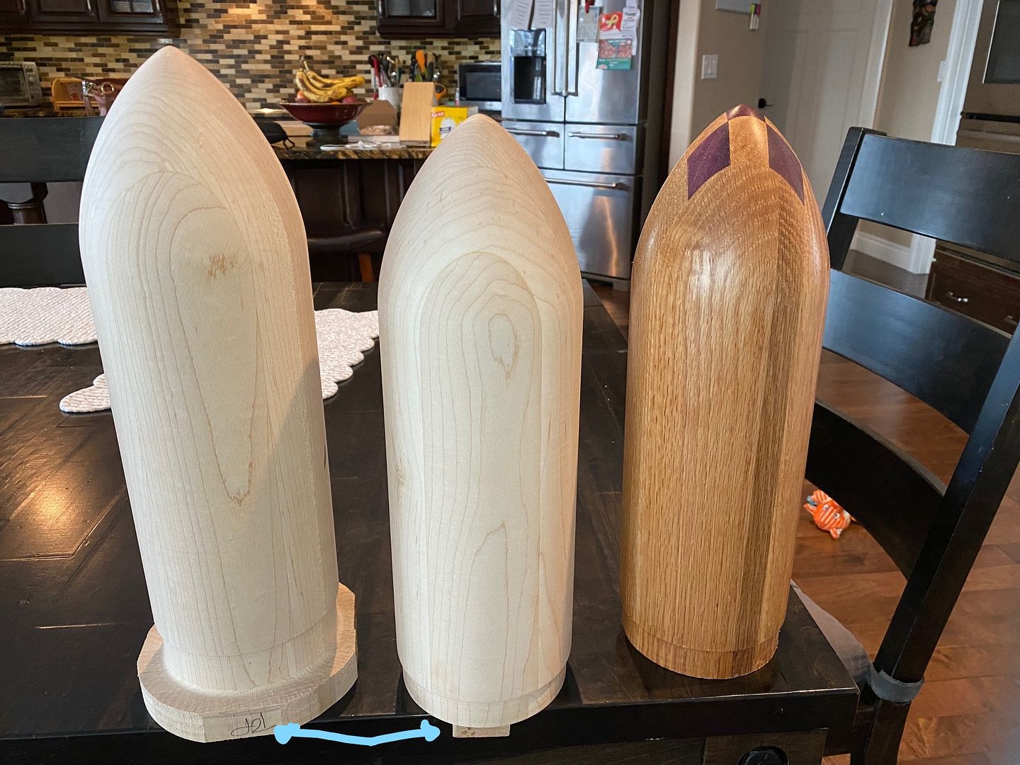 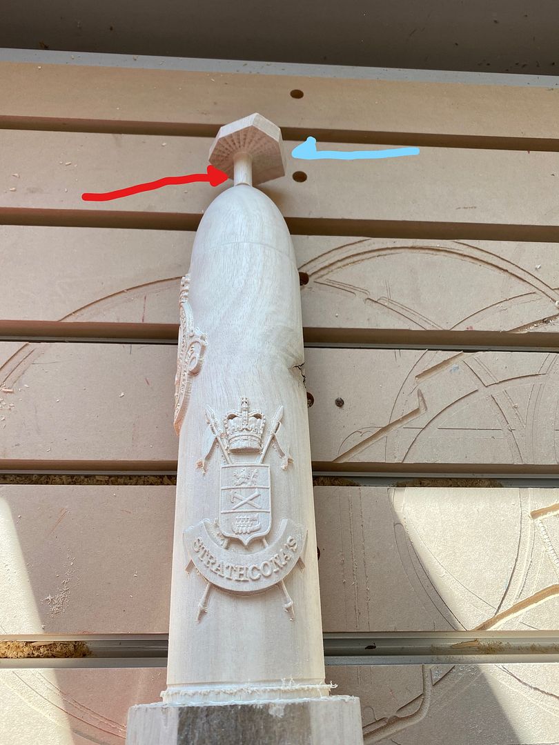 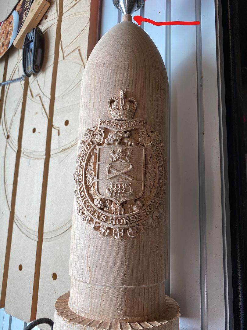 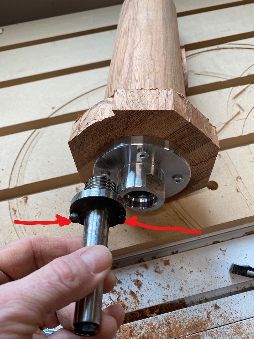 .jpeg) .jpg) I know that this post exceeded the scope of your question, but I too have felt the pain of having to deal with less than stellar documentation on this item (the only real help I have found is "Southern Ginger" (Zack Manring) and his YouTube videos, since he approaches from an end-user point of view, not from a tech wonk (such as the photos of the circuit boards, which I received from Axiom, with me trying to decipher what they meant (the first photo shows which controller is the A-Axis, and you have to follow the wires up to the correct piece, and the second shows the screw to turn (it's plastic, so be gentle!). The rotary axis gives one a lot of options for creating interesting pieces (rather than just making 2-sided pieces or doing them in slices and gluing them together) but it is not nearly as beefy as I would have liked. I am thinking about swapping out the stepper motor for one that has more torque, but I don't know if that is possible, due to size constraints of the housing (ie a more powerful stepper motor is probably too big for the case). Allan |
|
|
|
Post by grossmsj on Jan 22, 2022 19:20:21 GMT -5
Hi aluomala Wow, I'm really at a loss for your generous response. Between your info and joeblow I made good progress today. Felt like I was getting nowhere most of the day but I kept after it since I knew your approach worked. I'm almost there. I have to solve the simultaneous issues with Aspire, but I can see its going to work now. I'm glad for the additional insights on how you set up your work. It's good to see how people approach it taking into consideration practical limitations. That sort of thing would take noobs like me a while discover. Those tank rounds are impressive! Really cool stuff, and I'm sure they were very much appreciated in the commemoration event you make them for. I'm hoping I can get the wrapped designs in hand like you have. Do you think the torque limitations are related to size of the piece? I haven't seen that get, but I'm still getting started. I'm sort of hoping that since my machine is new, they may have made those adjustments part of current production. Scott |
|
|
|
Post by aluomala on Jan 22, 2022 21:30:13 GMT -5
Hi aluomala Wow, I'm really at a loss for your generous response. Between your info and joeblow I made good progress today. Felt like I was getting nowhere most of the day but I kept after it since I knew your approach worked. I'm almost there. I have to solve the simultaneous issues with Aspire, but I can see its going to work now. I'm glad for the additional insights on how you set up your work. It's good to see how people approach it taking into consideration practical limitations. That sort of thing would take noobs like me a while discover. Those tank rounds are impressive! Really cool stuff, and I'm sure they were very much appreciated in the commemoration event you make them for. I'm hoping I can get the wrapped designs in hand like you have. Do you think the torque limitations are related to size of the piece? I haven't seen that get, but I'm still getting started. I'm sort of hoping that since my machine is new, they may have made those adjustments part of current production. Scott Re the torque limitations being related to the size of the piece: that is a good point, and I wonder if they factored that into the original design/build process, or did they just use a standard (read as: cheap) stepper motor. More expensive parts results in more expensive products, but for the sheer heft and overall beefiness of the rotary axis body/frame/etc, it seems odd to cheap out on the stepper motor. One has to be VERY conservative with toolpaths/strategies. One thing I have taken to doing to avoid loss of steps is to run the toolpath up and down the y-axis (vs spinning the a-axis) since it seems to me that with heavier pieces (my tank rounds start off around 5.5" diameter and 15inches long) that if the rotary axis is whipping back and forth, the chance of losing steps is higher than if I go up/down the y-axis (minimal a-axis spinning). I may re-visit using the spinning toolpath (completing a revolution on the a-axis before moving forward/back on the y-axis. The wrapped designs do require one to "think" differently, since it isn't a simple flat slab of material, and if you want to have a design wrap around the piece seamlessly, that might be maddening (I haven't attempted it yet). One issue that made me approach the design process slightly differently was putting the unit crests on the tank round, all the way around, not just on the front/top. What I first envisioned doing was placing a model smack dab in the center (front) and then the back would have me cutting the model in half, and placing the respective halves on the sides and then when Aspire "wraps" the crest models onto the model I have made of the tank round, everything will be great, right? Not always. See photos below. 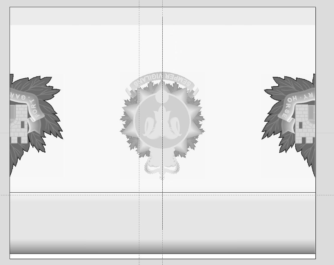 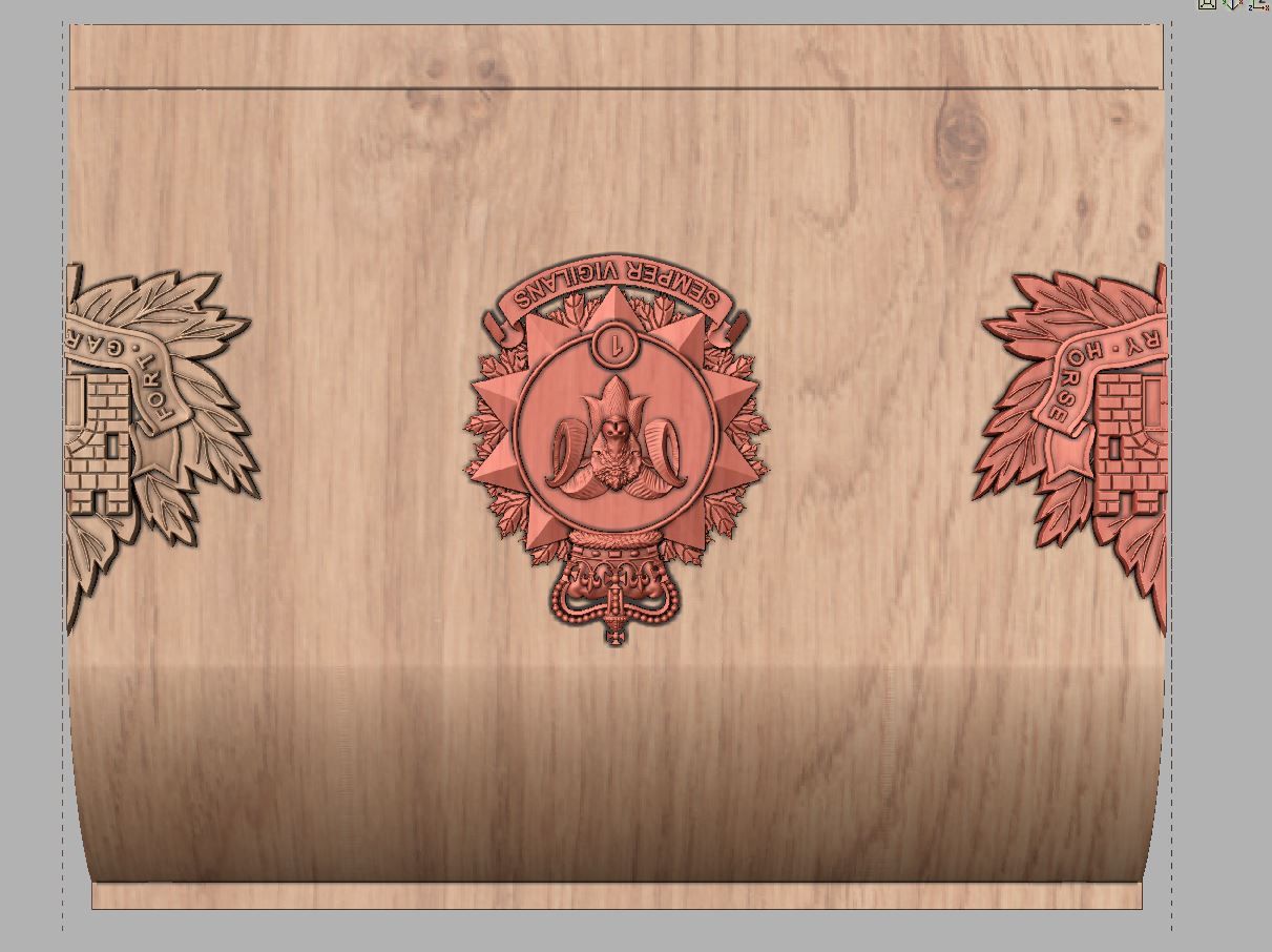 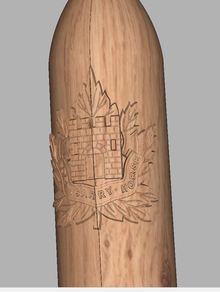 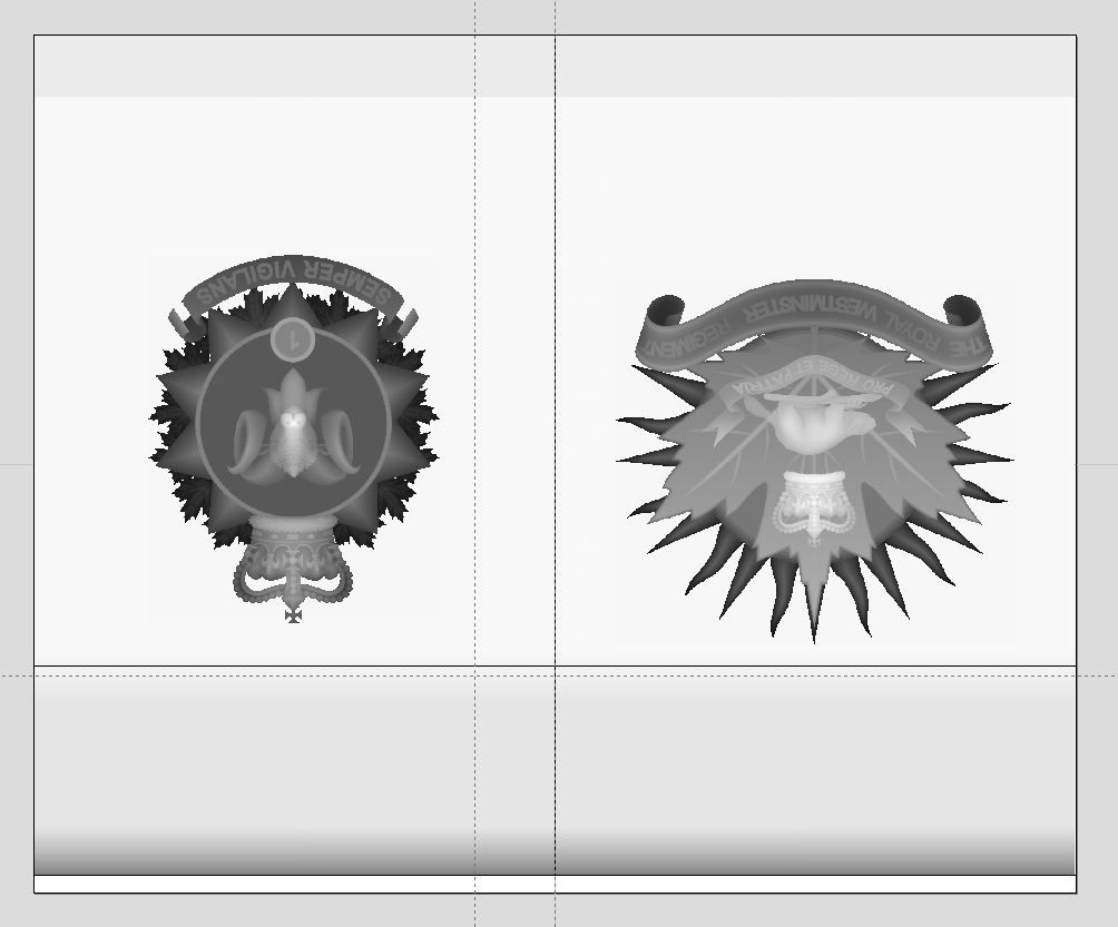 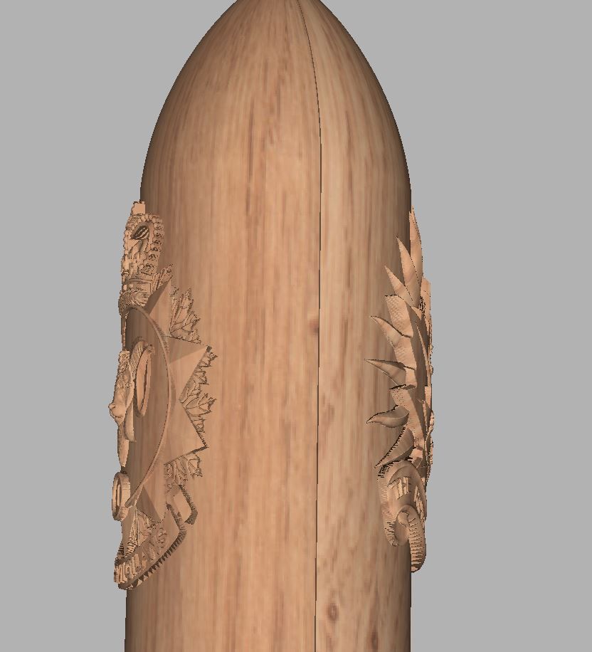 As you can see, looking at the problem from a slightly different position (ie where to place the models) can end up saving time (not having to slice a model in half, and then try to make sure it lines up at the seam) and having better overall results. I like to think of the wrap/unwrap method like designing a label for a soup can: you don't want the main image to have the label edges where they overlap, running down the middle. I avoid working with the models in the wrapped mode (3d) since it takes so long to update the graphics. Being able to jump in/out of those views is very handy, since the flat/unwrapped model might look good laid out flat, but when you jump into 3D mode (wrapped), you will spot any issues due to stretching on curves, etc. Hope this helps with the wrapping issues that you are experiencing. Allan |
|
|
|
Post by joeblow on Jan 23, 2022 6:34:25 GMT -5
Great info Aluomala and those pieces look awesome! Been wanting to see some of your rotary work so thanks for posting those pics. I imagine each one of those takes quite a long time on the rotary.
Glad your on your way Grossmsj.
Only other tip I could add is in regards to setting Z0. Somewhere in the menu is a setting to retract the spindle to a designated height after tool touch off with the puck. I set that to 50mm above the puck. This way when the bit touches off the puck it will raise 50mm up and place the bit at the centerline of the rotary. I can then set ZO without having to manually raise Z that 50mm. Quick and automatic each time as long as you remember that you need to re-set Z0 after puck touch off. This is the only time I use the puck for setting Z but that is another topic.
|
|
|
|
Post by aluomala on Jan 23, 2022 15:44:45 GMT -5
Great info Aluomala and those pieces look awesome! Been wanting to see some of your rotary work so thanks for posting those pics. I imagine each one of those takes quite a long time on the rotary. Glad your on your way Grossmsj. Only other tip I could add is in regards to setting Z0. Somewhere in the menu is a setting to retract the spindle to a designated height after tool touch off with the puck. I set that to 50mm above the puck. This way when the bit touches off the puck it will raise 50mm up and place the bit at the centerline of the rotary. I can then set ZO without having to manually raise Z that 50mm. Quick and automatic each time as long as you remember that you need to re-set Z0 after puck touch off. This is the only time I use the puck for setting Z but that is another topic. Thanks! Those aren't even my nicest pieces. I kind of got into making them for a spell, and didn't post pictures anywhere except my FaceBook business page. See below for my "nicest" pieces (more complex designs, really, not necessarily the "best" pieces I have done). To be honest, I am keeping some of my "secrets" somewhat close to my vest, since it took me a LOT of trial and error to come up with workable methods to accomplish this (as far as I can tell, I am the only person in Canada, and perhaps N America, making these items, so I want to keep my niche) but I don't mind sharing the basics, since there is a huge lack of information in regards to making things on the 4th axis, particularly with the Axiom, and with Aspire as well (many of the people making things on the 4th axis are using more advanced CAD/CAM software like PowerMill, which allows for X and A axis movement at the same time. One of the biggest timesavers I have found is to prepare the wood blanks using traditional methods (using table saw to remove corners and move to the lathe to roughly round the piece to specs (with the larger 105mm rounds, they start off at around 5.5" in diameter, just shy of the maximum that the AR4/8 series will allow. I am not sure, but I believe the Elite series allows for 8" of gantry height vs the 6" for the AR* series machines, so I think it might be possible to create risers for the rotary attachments to allow for larger diameter pieces since it has the extra headroom. As it is, I have to use shorter bits for the roughing process (I use 1/4" endmills for the roughing pass for all of my 3D carvings) since when I put the spindle over the piece (when it is still roughed out from the lathe), I have maybe 1/2" maximum of wiggle room. Using the faceplates helps with the process, since I can prep them in advance and I can get exact alignment even after taking it on/off my machines (whether it's the CNC or the lathe). 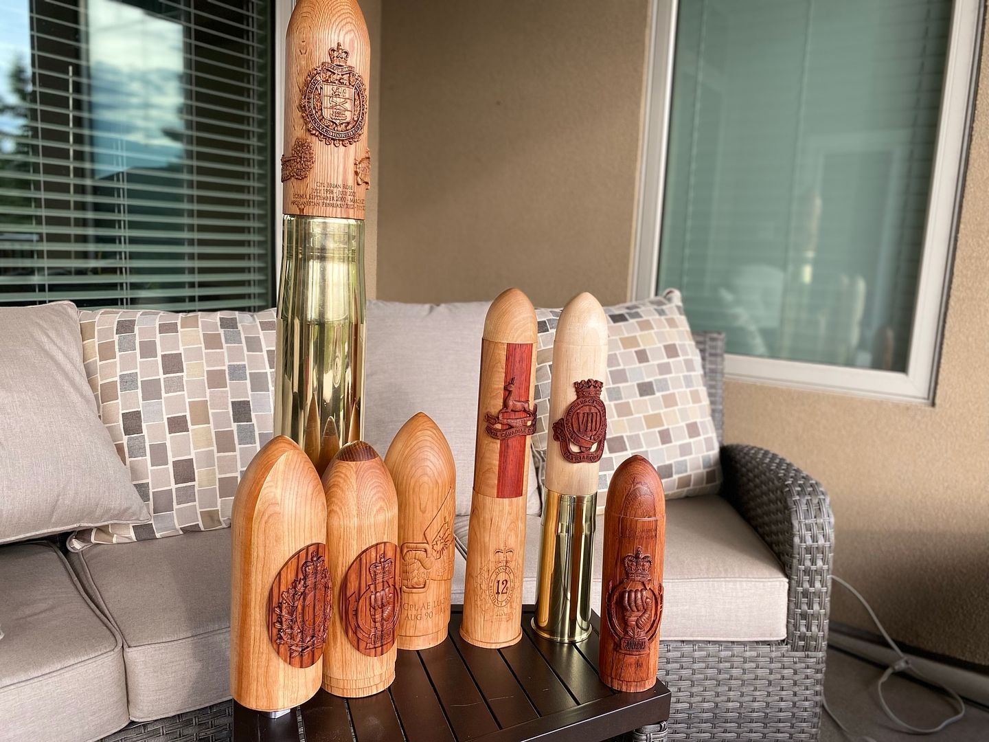 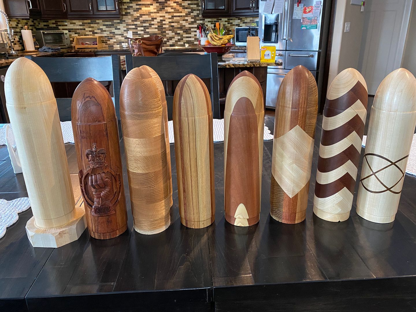 .jpg) The photos I included show a progression of how my pieces evolved: I started off relatively simple (one crest, with a few lines of text) using a single block of wood (maple, mostly, since I received a ton of it in exchange for making some of these tank rounds) and then started trying out different glue up techniques, both for visual interest, and as a way to save on wood ( a large portion of the wood is removed anyway, and if the center is hollow, that will save on weight, since most of my customers live away from me). I discovered 2 things: my customers are VERY conservative, and want relatively plain pieces (simple maple with a few crests to denote their service) and any savings in wood costs are offset by increased labour costs (for the most part) since it is generally far easier to glue up about 5 or 6 boards into a (roughly) 6" x 6" block than it is to cut, glue up and mess with weird shaped pieces of wood, all to save about half a board foot in wood. I further evolved my process to allow for multi-piece projects: the main tank round body in one type of wood (again, maple or cherry, due to cost, availability, etc) and then the crest done in another. This part of the process is what I generally keep to myself, although to be honest, it's not as hard as one might think. It involves the use of all the tools at my disposal: table saw, band saw, lathe, CNC (in "regular" mode and rotary axis mode) and using Aspire software. I started (the process of making the crests separately) approaching it one way (carve out crest on the rotary axis using laminated wood strips (hexagon or octagon), and then hollowing out the back on my lathe, using a LARGE forstener style bit (easier for the 76mm (3" diameter) heads than the 105mm (4" heads, believe me) and a spindle sander to get it to shape (3" or 4" diameter on the backside) so I can glue it to the tank round head. That way is not recommended, for any number of reasons: safety, requires large relatively expensive bits (about $50 each), time required, and lack of repeatability and precision. I also went down the rabbit hole after I saw some cool glueups on Pinterest, mostly from the pen making world, as well as rolling pins. Again, my customers are conservative by nature, so the "fancy" ones didn't go over well (at all). My improved method involves more CNC work, but is MUCH more accurate and reliable and I can create a bit of an assembly line process for the blanks, so I can react more quickly if someone wants one of these in a hurry (I can have blanks of the tank rounds already sanded and finished, and I can create one of the crests in a few hours, sand it and finish it and apply it to the already finished head (I can also add custom text if required, since I either leave the faceplate mounted (I have about half a dozen each of the 2" and 3" faceplates) or I leave the end unfinished so I have the screw holes still there to attach the faceplate). Unfortunately, I grossly overestimated the demand for something like this, due to 2 considerations: the type of tank rounds that these are based off of are obsolete, and it's only the older generation of soldiers (I joined in 1988) that fired these rounds, who consequently have a nostalgic attachment, as well as actually having the brass casings that they mount on. I don't sell the casings (they are VERY hard to find, via government surplus, and one must buy 5000 pounds of them at a time, at roughly $1 per pound, and they are severely damaged since they get handled pretty roughly, both on the ranges, as well in the recycling process). The new tanks that we use (Leopard2) fire 120mm rounds, and they use caseless technology (the casing itself is combustible, and the only thing that remains is the very bottom few inches (referred to as an ashtray)). Anyway, it all made for an interesting journey, both in the CAD/CAM design process; using traditional carpentry/woodworking skills and just general problem solving in general. If anybody has any questions on how I accomplished a given task, feel free to ask in a messenger post, since I'd prefer to keep my "corporate knowledge" of this under wraps somewhat, but I also want to help out members of the community, since I hate seeing people "stovepiping" things (keeping information to themselves, in a "stovepipe" fashion) rather than helping out others. I've seen a lot of oldtimers on forums express amazement that people share any knowledge, since "back in my day, nobody helped nobody!" and kept everything a trade secret. But those guys likely never learned anything other than what they already knew, so....... One note, on the last piece that I posted a picture of: if you notice the very top of the round, where I put the parachutist wings (along with the text), you might notice that it is slightly distorted, but that is due to the way that Aspire "wraps" the model. Because of this distortion, if you wish to do something similar (perhaps on a wine bottle, on the shoulder), you will have to factor in that distortion if you want the model to look correct. I vaguely remember seeing something in my rotary travels, that when you import a model into Aspire, it asks you if you wish to correct the distortion (or similar), but due to the nature of my "process" (once I have a working version of something, I keep re-using that version, warts and all, and don't start from scratch on every project), so I have never seen that option appear again when working on pieces that used my "template" model(s). Might have to investigate that, and likely re-work my "template" files so I am using the best version possible. Allan |
|
|
|
Post by grossmsj on Jan 24, 2022 6:46:18 GMT -5
Thank you Allan, It is easy to see why these would be so popular. You have the emotional connection to service, nostalgia, and really nice craftsmanship. Add on each piece can be personalized and I can see where everyone who spent any significant time with tank gunnery in their past would want one. I've finally gotten this to work now, more or less just the way I want it too. Fixing that origin near the headstock is the way to go, for sure. Today I'll make up a raised touch off to zero the y-axis at 75mm. I had a bit of excitement when I changed bits and didn't think through the right way to re-zero the bit. Completely shreaded a carbide bit into the tailstock and blew a fuse in the Siemens controller.  I was left with some indelible memories and scratches to the tail stock, but it's all working fine now. I'll be doing stool leg spindles to start, and also want to do some things with peppermills. The process for the spindles will be simple, but the peppermills will be more complicated because they have to be hollowed out and the form needs to be absolutely concentric with the central axis of the hollowed interior. I think I'll need a different chuck, for sure, and will probably need to use a different tail live center. I've got an older Oneway Talon chuck that will work fine, I just need a new thread adaptor. I also need to learn how hard I can 'push' processes like the roughing cuts to speed things up. Totally understand wanting to keep some of the hard-earned critical lessons to yourself. I'd be the same way. Craftsmanship is hard earned. I truly appreciate what you and joeblow have shared to get me going. I don't mind grinding through the learning if I know something is technically possible. But right now, I'm sort of drinking from a firehose and just trying to figure out the starting basics. Good to see meaningful progress every day. Scott |
|
|
|
Post by aluomala on Jan 24, 2022 21:09:35 GMT -5
"I also need to learn how hard I can 'push' processes like the roughing cuts to speed things up. "
That right there is priority #1, if you are planning on doing production runs. If you are making one-off things once in a while, slow and steady is fine, but I find (generally) that people baby their machines (like using 50IPM and shallow depth of cut (DOC)) and go way slower than they need to. The weak link with the rotary axis attachment is definitely the weak stepper motor, and it forces one to use slower speeds out of necessity. When I first started with the rotary axis, I actually thought I got a damaged/broken device, since I could very easily rotate the chuck by hand, and my first few cuts (using the rounding gadget to make the square/rectangular blanks to round) were disappointing, loosing steps constantly. I eventually came up with more conservative settings that minimized the amount of slipping, but I haven't re-visited the roughing process to try to speed up the time required, going with the "if it ain't broke, don't fix it" mentality. The finishing toolpaths (I use pretty small bits for the detailed areas, like 1/32"r tapered ball nose (TBN) and 1/16"r, and 1/8"r for the flats) aren't really an issue, so I can go reasonably fast with those (same as for traditional flat machining).
Hopefully it doesn't take you too long to find your groove with the rotary axis, since it does open up a lot of different possibilities, but I sometimes think I would have been better off coming up with strategies like 2-sided machining, or using slicing, to create some of these items. Live and learn, I guess....
|
|
|
|
Post by grossmsj on Jan 26, 2022 16:08:53 GMT -5
Hitting the groove with spindles.  It's down to some of the fine stuff with Aspire. But I have to say I'm really loving how this is going now. The results are very, very promising. Still cutting in scrap pine lumber until it's just right. But the cherry is a day away. Ain't no babyin' going on anymore, but I sure started that way. The first roughing cut with a 1/4" end mill on a 24.5 inch by 1.5 inch spindle took somewhere around two hours! It was also strange this time was way longer than Aspire said it would take. Long story short, it's down to ten minutes now. Plowing through it with a 1/2 inch end mill with 0.2 inch passes. It also helped to look at how the finishing cut worked in order to figure out how to readjust the roughing cut. With the defaults from Aspire (Z-level with 0 degree raster angle) there was a lot of wasted time just rotating the spindle back and forth. Changing the raster angle to 90 degrees kept the bit cutting in the wood most of the time. It's going fast, to the point the wood is complaining about it. Seems pretty close to the edge and I can't see pushing it. I'm not seeing any slipping at this point, knock wood. It's pine, and narrow diameter, but I'm honking on it pretty hard and it's working like I'd expect. The chuck has to go though. Every time I tighten it down there's all sorts of funky stuff going on. As another poster mentioned, it seems really out of place with this machine. Plus, you can't change the jaws so it is a one trick pony. Thanks again for your help getting me started!  ![]() ![]() |
|
|
|
Post by aluomala on Jan 27, 2022 13:08:18 GMT -5
Hitting the groove with spindles.  It's down to some of the fine stuff with Aspire. But I have to say I'm really loving how this is going now. The results are very, very promising. Still cutting in scrap pine lumber until it's just right. But the cherry is a day away. Ain't no babyin' going on anymore, but I sure started that way. The first roughing cut with a 1/4" end mill on a 24.5 inch by 1.5 inch spindle took somewhere around two hours! It was also strange this time was way longer than Aspire said it would take. Long story short, it's down to ten minutes now. Plowing through it with a 1/2 inch end mill with 0.2 inch passes. It also helped to look at how the finishing cut worked in order to figure out how to readjust the roughing cut. With the defaults from Aspire (Z-level with 0 degree raster angle) there was a lot of wasted time just rotating the spindle back and forth. Changing the raster angle to 90 degrees kept the bit cutting in the wood most of the time. It's going fast, to the point the wood is complaining about it. Seems pretty close to the edge and I can't see pushing it. I'm not seeing any slipping at this point, knock wood. It's pine, and narrow diameter, but I'm honking on it pretty hard and it's working like I'd expect. The chuck has to go though. Every time I tighten it down there's all sorts of funky stuff going on. As another poster mentioned, it seems really out of place with this machine. Plus, you can't change the jaws so it is a one trick pony. Thanks again for your help getting me started! <button disabled="" class="c-attachment-insert--linked o-btn--sm">Attachment Deleted</button> ![]() ![]() Re the raster angle set to 90: that is exactly what I do, both for the lessened wasted(?) rotations, which I imagine would minimize lost steps, as well as the reason you mentioned: it allows for the machine to be aggressive to the point where you can manage speeds better for reduced cutting times. I see lots of people (regarding "regular" carves (3D or 2d)) using 45 degree angles as a method to reduce fuzzies, etc, but I have stopped doing it since A) it seems to me that it seems to be less than optimal from a speed point of view and b) it doesn't (for me anyway) seem to give any advantages. If I get a vertical or horizontal line on my piece (from where there is a height difference where the paths meet up), it can easily be sanded off (usually) and even if it can't it usually looks "natural", line wood grain or perhaps a wood defect. If it's on a perfect 45 angle (relative to wood grain), it looks artificial/man-made. I think self-taught CNC guys like me try to do what they think works best, without understanding the purposes of raster vs offset, or climb vs conventional, because wood is so much more forgiving than metal, so sometimes you just use the defaults (or what you read on a forum post, tutorial, etc) because that is what seems to work. Sometimes going "against the grain" (figuratively, not literally) is the best approach, since if "you always do what you've always done, you'll always get what you've always gotten", which can be good, or bad, depending on your outlook. An example of this is the bit of choice for doing the roughing toolpath: I started off using a regular end-mill (1/4" usually), but I started to notice lines on my 3D carvings, and as it turned out, with the 3D carvings that had relatively steep sides or curves, there was a witness line (I think that's the right term) where the 1/4" endmill dug too deep, and the taper ball nose didn't clean it up. A ballnose bit (spiral) prevents this, and in my experience, doesn't seem to be much slower than using an end-mill. You can also increase the tolerance (how much is left by the roughing pass), but once I got used to it, I have been doing it ever since. It looks like you're getting things figured out in a hurry, so I look forward to seeing what you can make with the machine. Allan |
|


 I was left with some indelible memories and scratches to the tail stock, but it's all working fine now.
 It's down to some of the fine stuff with Aspire. But I have to say I'm really loving how this is going now. The results are very, very promising. Still cutting in scrap pine lumber until it's just right. But the cherry is a day away.
 It's down to some of the fine stuff with Aspire. But I have to say I'm really loving how this is going now. The results are very, very promising. Still cutting in scrap pine lumber until it's just right. But the cherry is a day away.